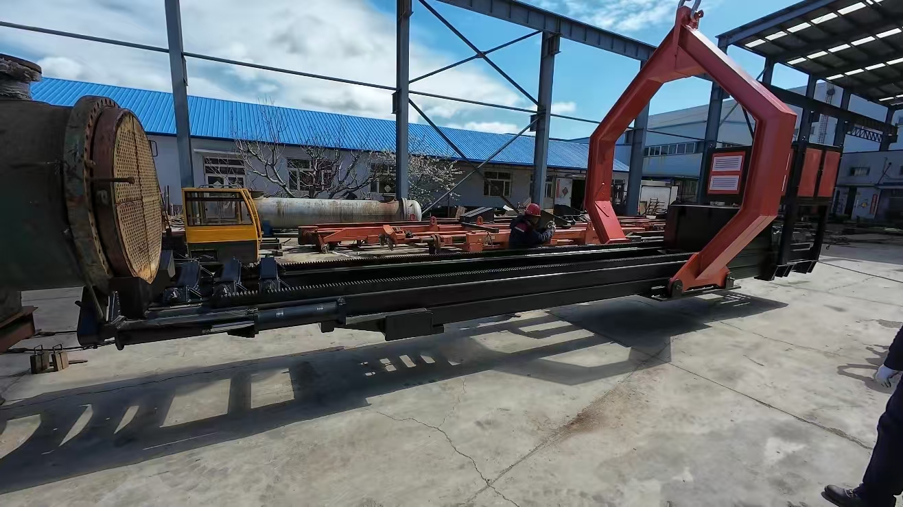

Bundle puller is a device used for the installation and removal of heat exchanger tube bundles. Its structure mainly includes the following parts:
Firstly, a bundle puller usually has a frame, which serves as the supporting structure of the entire equipment. The side beams on both sides of the frame are equipped with lifting lugs, and the inner cavity of the guide rail is equipped with hydraulic pipelines and electrical control lines; the bottom beam adopts a hollow structure, one of which is used as the hydraulic pipeline leading from the hydraulic oil cavity and is connected to the hydraulic cylinder; the inner cavity of the other bottom beam is equipped with an electrical controller.
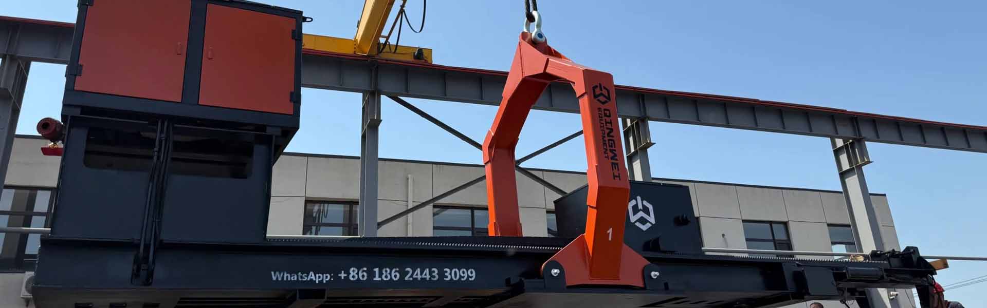
Secondly, the main traveling crane is an important part of the bundle puller. The main traveling crane is equipped with a pushing device, which can adopt a new type of rotary folding pushing device to realize 180-degree flipping through a worm gear, greatly improving the time of the pushing device in the process of extracting the tube bundle. The main traveling crane is equipped with a driving device and its connecting rod under the main plate, and the connecting rod can drive the hanging plate set at the front end of the main traveling crane to rise and fall. Some main traveling cranes are equipped with a clamping mechanism on one side for clamping the end plate of the tube bundle, including a lifting plate, a supporting plate and a clamping plate, and the main traveling crane is equipped with a lifting member for driving the lifting plate to rise and fall. Others can adjust the angle of the heat exchanger tube bundle, including the main traveling crane body, the cylinder seat, the cylinder, the piston rod of the cylinder, etc., using a hydraulic drive structure with compact and powerful force.
In addition, the bundle puller also includes a small traveling crane, clamping feet, a power mechanism and a transmission mechanism, etc. A handle device is provided at the front of the frame, and the handle device includes a handle cavity formed by a load-bearing plate, a plurality of handle side plates, and a handle plate located at the top. A lifting device for lifting the handle plate is provided in the handle cavity, and the height of the handle plate can be lifted by the lifting device to receive tube bundles of different diameters and fine-tune the position of the tube bundle. Some tube bundle extraction and installation equipment is also equipped with a lifting structure, such as an integrated lifting plate with inclined plates at both ends, which uses the lifting points of each other as the supporting points of each other, greatly increasing the force arm to achieve an increase in the lifting force.
Some bundle pullers are also equipped with a take-up structure, including a rewinding machine bracket, two support plates are provided below the bracket, and a fixed plate, a fixed shaft, a rewinding roller and a rewinding turntable are provided between the support plates for regularizing and extending the cable.
In conclusion, the bundle puller has a relatively complex structure, and each part works together to achieve efficient and safe extraction and installation of the heat exchanger tube bundle.
The frame structure of the bundle puller plays an important supporting role in the entire equipment. The maximum load capacity of the frame can reach 30 tons, and the material is Q235B. The frame guide rail has a high straightness requirement, and the length of 1000mm is less than 0.2mm. Components such as the traction motor, worm gear reducer, drive sprocket and drive chain of the transmission system are installed on the frame. The worm of the gearbox is made of 45# quenched and tempered treatment, and the hardness is HB275-295; the worm gear of the gearbox is made of ZQAL10Fe3 inlay; the drive chain is made of 45Mn, and the single drive chain has a traction force of not less than 15 tons; the drive sprocket is made of 45# quenching, and the hardness is HRC38-42. The number of stages of the traction motor is not less than 4, and the power is not less than 11kW. The traveling speed of the main traveling crane is 1600-1800mm/min, and the main traveling crane and the following small traveling crane are installed on the frame guide rail to realize the extraction and installation of the tube bundle.
The structure of the main traveling crane of the bundle puller is relatively complex. The main traveling crane consists of the main traveling crane body, the cylinder seat, the cylinder, the piston rod of the cylinder, the movable pulley block, the wire rope, the fixed seat, the fixed pulley, the positioning lug and the heat exchanger tube bundle. The cylinder seat is detachably arranged on the top of the main traveling crane body, the cylinder is detachably arranged on the right side wall of the cylinder seat, and the cylinder is provided with a piston rod of the cylinder, and the right end of the piston rod of the cylinder is provided with a movable pulley block. The top of the main traveling crane body is provided with a steering pulley, and the steering pulley is located at the rear side of the cylinder seat; the front and rear side walls of the main traveling crane body are provided with steering pulleys; two fixed pulleys are arranged on the front and rear outer walls of the main traveling crane body, and are located on the left side of the steering pulley. The heat exchanger tube bundle is arranged at the left end of the main traveling crane body, and the positioning lug is arranged on the front and rear sides of the outer wall of the tube bundle of the heat exchanger. The fixed seat is arranged at the top corner of the front and rear side walls of the cylinder seat, and one end of the wire rope is fixedly arranged on the two fixed seats, and the other end of the wire rope bypasses the movable pulley block, the steering pulley, the steering pulley and the fixed pulley, and is hung on the positioning lug. The movable pulley block includes four pulleys, and the four pulleys are arranged in a rectangular shape, and each two diagonal pulleys are in the same direction.
Although the structure of the small traveling crane is relatively simple, it can be known that the small traveling crane and the main traveling crane are installed on the frame guide rail together, and the following small traveling crane is equipped with a supporting plate that can move up and down to support the middle partition of the tube bundle.
The structure of the handle device of the bundle puller includes a handle cavity formed by a load-bearing plate, a plurality of handle side plates, and a handle plate located at the top. Two identical handle side plates are arranged side by side, and the top surface of the handle side is an inclined surface. The two handle side plates are connected as one through the handle plate shaft at the high end of the inclined surface. The handle plate is a two-section bent plate structure. The lifting device is arranged at the lower part of the bottom side of the handle plate and is connected with the handle plate through a bevel hinge, and the lifting device is a hydraulic cylinder. On the upper part of the hydraulic cylinder, a dust cover for the hydraulic cylinder is movably installed between the end of the handle plate and the rear vertical handle side plate. A supporting vertical plate is also provided on the lower side of the handle plate, including a supporting vertical plate I, a supporting vertical plate II, and a connecting plate installed on the upper parts of the supporting vertical plate I and the supporting vertical plate II. The height of the supporting vertical plate II is higher than that of the supporting vertical plate I, and the inclination direction of the connecting plate is the same as that of the handle plate. A side balance cable chute is fixedly installed on the outer side of the supporting vertical plate II, a side balance cable ferrule is provided at the bottom of the side balance cable chute, and a chute reinforcing rib is provided at the top. An inner guard plate is fixedly installed at one end of the load-bearing plate, and an oil pipe guard plate is also provided at one end of the inner guard plate. A side plate reinforcing rib is provided at the lower outer side of the handle side plate.
The lifting structure for the tube bundle extraction and installation equipment includes a base, a lifting mechanism and a lifting plate. The base is an open groove type, and the lifting plate is an integrally formed plate with a concave middle and symmetrical raised ends. The lifting mechanism is installed at both ends of the base, and the lifting plate is placed in the open groove, and the ends of the left and right inclined plates are respectively installed on the lifting mechanism, using the lifting points of each other as the supporting points of each other, greatly increasing the force arm to achieve an increase in the lifting force.
The take-up structure of the bundle puller includes a rewinding machine bracket, and two support plates are provided below the rewinding machine bracket, and a fixed plate, a fixed shaft, a rewinding roller and a rewinding turntable are provided between the two support plates. The two ends of the fixed shaft are threaded, and the left side of the fixed shaft passes through the middle of the fixed plate, and the left end of the fixed shaft is fixed on the support plate through a nut. The rewinding roller and the rewinding turntable are fixedly connected to each other.
The bundle puller is a device used for the extraction and installation of heat exchanger tube bundles, and its various structural parts cooperate with each other to complete the extraction and installation of the tube bundles. The frame provides support and installation foundation, the main traveling crane and the small traveling crane realize the movement of the tube bundle, the handle device is used to receive the tube bundle and make fine adjustments, the lifting structure provides lifting force, and the take-up structure facilitates the organization of the cable. The reasonable design and cooperative work of these structures make the bundle puller play an important role in the maintenance and installation of heat exchangers.